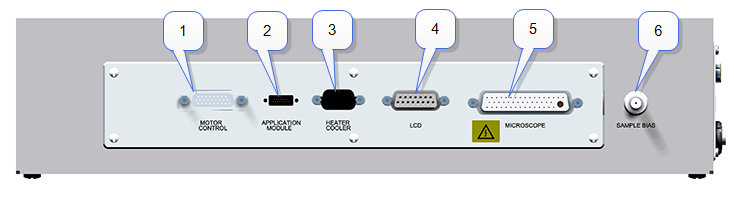
Connect the following cables from the back of the Dimension Icon microscope to the top of Electronics Box. See the table and figure below for a list of extensions, connection information, and connection locations.
| Figure Reference | Cable | Part Number | Box | Function |
|---|---|---|---|---|
| 1 | Motor Control Cable | Dimension Icon back panel | Motor control | |
| 2 | Application Module Sensor Cable, 15-pin D | 465-000-015 | Application Module | Application Module control |
| 3 | Heater/Cooler Serial Cable, 15-pin D | 820-017-606 | Heater/Cooler | Heater/Cooler control |
| 4 | LCD Serial Cable, 15-pin D | Dimension Icon LCD | LCD control | |
| 5 | Microscope Scanner Cable, 47-pin | Dimension Icon scanner | Microscope scanner control | |
| 6 | Sample Bias Cable, coax-SMA | Application Module | Sample bias control |
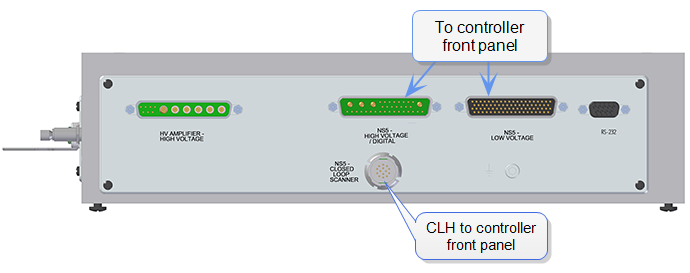
The Electronic box connections to the NanoScope V controller are located on the back panel:
| www.bruker.com | Bruker Corporation |
| www.brukerafmprobes.com | 112 Robin Hill Rd. |
| nanoscaleworld.bruker-axs.com/nanoscaleworld/ | Santa Barbara, CA 93117 |
| Customer Support: (800) 873-9750 | |
| Copyright 2010, 2011. All Rights Reserved. |
 Related Topics